
UniFi's Advanced Wi-Fi Settings Explained
Originally Posted: November 23rd, 2021
Last Edited: September 2nd, 2024
UniFi’s advanced Wi-Fi settings are often misunderstood. While the defaults are usually safe, having a deeper understanding of each setting is helpful when configuring a network or troubleshooting an issue. The tooltips in the interface cover the basics, but we’ll explore them in depth.
The screenshots show UniFi Network Application version 8.4.59, running on a Cloud Gateway Ultra. If you are using a different version or have different hardware, you might not see the exact same things. Most of the interface is the same between a Cloud Gateway and a self-hosted setup, but some settings may have been added, renamed, or moved if you’re running an older version. I’ll point these out along the way.
This guide doesn’t cover everything and it is not perfect. I try to be accurate and keep this up to date, but Ubiquiti’s documentation and your real-world experience should always be trusted over what you see here. If you notice any inaccuracies or have a suggestion, please let me know.
Table of Contents
- Feature History & UI Overview ↩︎
- Creating a New Wi-Fi Network ↩︎
- PPSK, Guest Networks, & Wi-Fi Band ↩︎
- Advanced Wi-Fi Settings ↩︎
- Band Steering
- Hide WiFi Name
- Client Device Isolation
- Proxy ARP
- BSS Transition
- UAPSD
- Fast Roaming
- WiFi Speed Limit (Bandwidth Profile)
- Multicast Management ↩︎
- DTIM, Rate Control, & Filtering ↩︎
- Security & Wi-Fi Scheduler ↩︎
- Global Settings & Radio Manager ↩︎
- AP Settings & Manual Control ↩︎
- Legacy UI Settings ↩︎
UniFi Advanced Wi-Fi Settings Explained — Updated for UniFi Network Application v8.4.59
UniFi Network Application Feature History
Since the software is constantly changing, it helps to know a little history and what version you are using before going through this guide.
8.4 - Passpoint/Hotspot 2.0, packet capture, AP analyzer, pro AV settings, and advanced IGMP snooping
8.3 - Custom NAT on UniFi Gateways
8.2 - Wi-Fi 7 MLO, Inspection tab, ACL rules, and BGP routing (requires UniFi OS 4.1)
8.1 - Network Viewer, NAT pools, L3 network and device isolation ACLs, OSPF routing, enhanced firewall rule visibility, side panels in the UI, and Innerspace for visualizing Wi-Fi coverage.
8.0 - Radio Manager, VLAN Viewer, Wireguard VPN Client, Site Overview, and a professional installer toggle for consoles
7.5 - Wi-Fi Private Pre-Shared Keys (PPSK), improved dashboard for WiFi-only setups, improved topology, latency testing, and DNS Shield
7.4 - OpenVPN Server, Port Manager, and IPTV IGMP proxy
7.3 - VPN client routing, ad blocking, and Wireguard VPN
7.2 - Local DNS records, automatic speed test, global network and switch settings, OpenVPN client, Wi-Fi performance section, and speed limits for Traffic Rules
7.1 - Teleport VPN, Traffic Routes, and switch port insights
7.0 - Global AP settings, improved settings and dashboard UI, per-network mDNS, New Device Auto-Link, MFA support, and auto backup
UniFi Network Application UI Overview
In the desktop web interface, the major sections are represented with icons:

UI Overview of UniFi Network Application v8.4.59 running on the Cloud Gateway Ultra
Creating a New UniFi Wi-Fi Network
In the UniFi interface, network settings are divided into Wi-Fi, Networks, and Internet.
Wi-Fi controls your wireless networks, including SSID, password, and other advanced settings.
Networks controls your LAN networks and VLANs, global network and switch settings, and some per-network security and filtering options.
Internet controls your WAN connections, including public IP addresses, PPPoE, UPnP, dynamic DNS, and Smart Queues for QoS.
By default, UniFi has one LAN network, 192.168.1.0/24, which is used for all wired and wireless connections. Creating additional virtual networks (VLANs) allows you to segment and restrict traffic. This is commonly used for guest or IoT devices, or separating devices or areas into different network groups. Before diving into wireless settings, setup your networks and VLANs first. This can be done by modifying the default LAN, or by creating a new virtual network under the Networks tab.
If the network you want to use has been created, go to Settings → Wi-Fi → Create New.
Give it a name (SSID), password, and specify which virtual network it is going to use. Then you can select which APs will broadcast this network. If you don’t want to use the default of a WPA2 password, toggle advanced to manual and scroll down to the “Security Protocol” tab. Otherwise, you can hit the blue “Add WiFi Network” button and your new Wi-Fi network will be created.
Creating a new UniFi Wi-Fi network in UniFi Network Application.
Broadcasting APs — AP Groups
This setting controls which APs will broadcast this Wi-Fi network. By default, it will be added to every AP. In multi-site controllers, it will be added to every AP in the current site. If needed, you can select individual APs or create a group of APs to broadcast this network.
UniFi APs have a limit of either 4 or 8 SSIDs per band, per AP group. Some older models like the AC-Lite only support up to 4 per band. Most models can have up to 8. This means you can have up to eight 2.4 GHz and up to eight 5 GHz networks, or eight dual-band SSIDs. The same applies to 6 GHz.
Enabling wireless meshing limits all UniFi APs to 4 SSIDs per band. This is because wireless meshing adds hidden SSIDs for other APs to connect to.
Default: All APs.
Recommendation: For smaller networks with only a few APs and no need to limit which APs are broadcasting, use the default “All APs” group. For larger networks, group APs by area or function. Each additional SSID adds overhead and reduces capacity, so you should try to use as few as possible.
If you want a basic network, hit the “Add Wi-Fi Network” button and you're done. If you want more, the good stuff is revealed when you change advanced settings from auto to manual.
Note: Since version 7 there is a warning that applying these changes is going to disrupt users that are currently connected. That is why you might see a triangle with an exclamation mark in the blue “Add Wi-Fi Network” or “Apply Changes” button on the bottom.
Every time you change a Wi-Fi network setting it triggers a provision, which sends the updated configuration to each AP. When it’s applied, connected clients will likely see a short pause in traffic, and possibly a disassociation from the network. It’s best to make changes on idle networks, or during times of low usage.
PPSK, Guest Networks, and Wi-Fi Band
PPSK: Private Pre-Shared Keys
Private PSKs (PPSKs) are unique pre-shared keys for individual users or groups of users. This feature allows a single SSID to represent multiple networks, each with different access or restrictions. Users will see a single Wi-Fi SSID but be directed to different networks based on the password they provide.
It’s possible to do the same thing with RADIUS, but depending on your requirements, creating a PPSK may be a simpler and better way. RADIUS is likely the better solution for something like employee wireless, where you want a valid username/password tied to network access. Creating a PPSK is a manual process, so maintaining hundreds of them isn’t scalable. If you have distinct groups - trusted users versus guests, or just need a way to cut down on the number of SSIDs you are broadcasting, PPSK may be a good fit.
Currently if you want to create a PPSK network you need to use WPA2, and you can’t use 6 GHz. You can’t use PPSK in combination with a hotspot or captive portal, or RADIUS MAC authentication.
In UniFi, configuring a PPSK network is simple if you already have your networks and VLANs configured. Disable WP3 and 6 GHz if needed, then select the network and define the password.
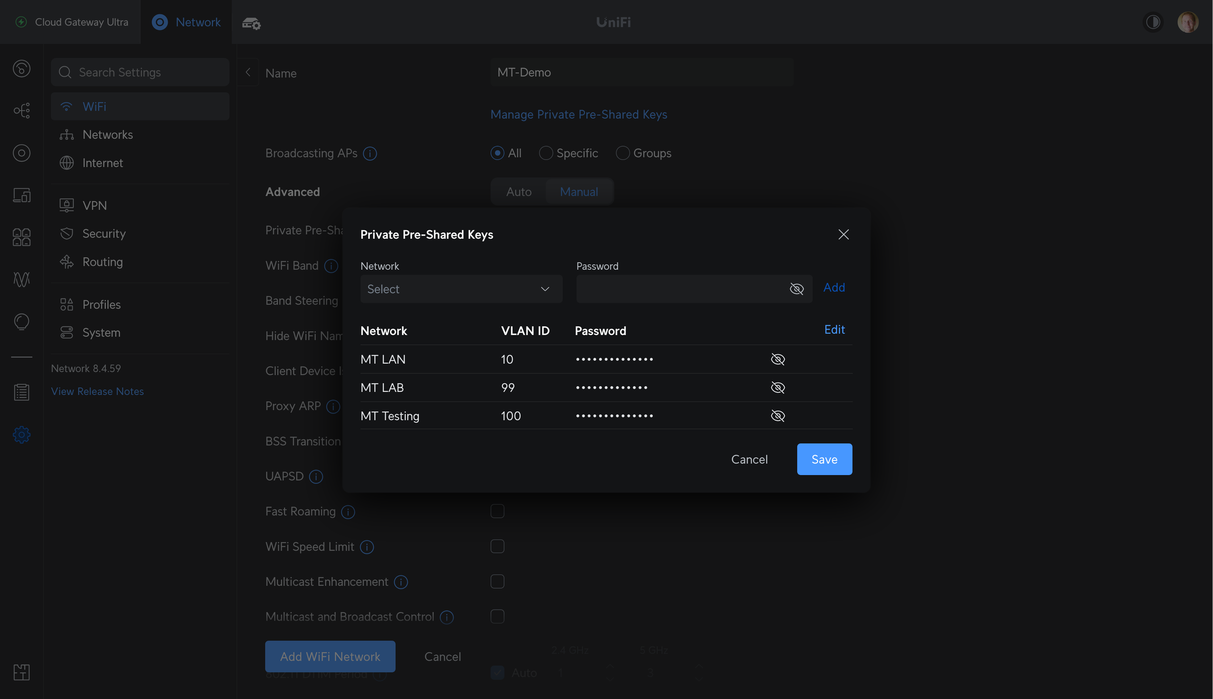
Creating a PPSK network
Guest Networks: Captive Portal and Passpoint
There are two options for Hotspot 2.0: Captive Portal or Passpoint.
Selecting “Captive Portal” will show a splash page when clients join the network. This could be used to redirect to a website, show a terms and services agreement, integrate with an outside authentication method, or prompt for payment. The settings for this are found under Insights -> Hotspot -> Landing Page. That is where you can change the guest wireless captive portal design, authentication, payment methods, and settings.
Default: Unchecked
Effect: Applies your captive portal settings and applies client device isolation.
Recommendation: Enable for networks meant for guests, where you want them to see a splash page, agree to terms and conditions, authenticate, or pay. Leave disabled on secured networks for trusted devices.
Note: In previous versions, this was referred to as Wi-Fi Type, which had a toggle between standard and guest hotspot.
Relevant help articles:


Passpoint
Another Hotspot 2.0 option is Passpoint, which was added in Network v8.4.54. Passpoint is built on the 802.11u standard and it improves network discovery, selection, and can enable cellular network offload to Wi-Fi. See this Ubiquiti help article for more details about Passpoint: Setting Up Passpoint on UniFi Network
Wi-Fi Band
Options:
2.4 GHz: Slow, long range, more wall penetration.
5 GHz: Fast, shorter range, less wall penetration.
6 GHz: Fast, shortest range, even less wall penetration. Limited device support, but lots of available spectrum to use wider channels. This requires a Wi-Fi 6E or Wi-Fi 7 access point. See my U6-Enterprise Preview for more details.
Default: 2.4 GHz and 5 GHz. If you have a Wi-Fi 6E or 7 AP, the option to add 6 GHz appears.
Effect: This setting controls which band your Wi-Fi network broadcasts on. You can pick one, or enable all of them.
Recommendation: Leave on dual-band, unless you have connectivity issues with 2.4 GHz devices or want manual control. Enable 6 GHz and change to WPA3 if you have the option.
Note: Dual-band or tri-band SSIDs with multiple access points can lead to roaming issues, with some clients staying on 2.4 GHz, or not roaming to the nearest AP. There are several ways to combat this. Usually adjusting AP placement, lowering 2.4 GHz transmit power, changing channels, or enabling band steering can be effective.
You can also create a separate network for each band if you want guaranteed, manual control over which band is used by which device. Otherwise, it’s up to the client device to do the right thing.
Advanced Wi-Fi Settings
Scrolling below Wi-Fi Band is where things get fun, and the acronyms take over.
Band Steering
Band steering forces compatible clients to move to 5 GHz. Previously with Band Steering enabled, client devices performing a passive scan would qualify the 2.4 GHz BSSID as hidden. A few years ago a newer method was added, which directs clients to 5GHz post-association using BSS Transition Management frames. This newer method causes less conflicts with older or 2.4 GHz only devices.
Default: On
Effect: Less clients will use the slow and often crowded 2.4 GHz band
Recommendation: Leave enabled, unless you have connectivity or roaming issues. As a normal troubleshooting step, disabling band steering is a good thing to try. It’s possible that band steering causes issues for your devices on your network, even though it doesn’t cause issues on mine.
Hide Wi-Fi Name
Default: Off
Effect: This forces access points to send out beacon frames with no SSID, meaning the SSID field in the beacon frame is set to null. To join a network with a hidden SSID, clients have to manually enter the SSID name along with the password. Beacons frames are still sent, and “hidden” networks are still easy to detect.
Recommendation: Leave disabled. Hiding the SSID does not enhance the security of the network. Hidden networks can still be scanned, found, and joined. Using 802.1X or a more complex password, moving to a newer protocol (WPA2/3 vs. WPA or WEP), or configuring firewall/traffic/ACL rules are better ways to improve security.
Client Device Isolation
Client device isolation prevents clients on the same AP from communicating with each other. Together with network isolation, switch ACLs, and traffic/firewall rules, it can prevent clients from reaching other clients or other networks or specific devices.
Default: Off
Effect: Restricts clients on the same AP from communicating with each other.
Recommendation: Enable on high-security guest networks, or IoT networks that would benefit from this restriction. If you have a full UniFi network, enable “Network Isolation” to isolate the network from your other internal networks, and configure traffic and firewall rules as needed.
Enabling this can lead to unintended consequences and prevent AirPlay, Chromecast, Sonos devices, screen mirroring, and wireless printers from working. Test device behavior before and after changing this setting.
Note: Client device isolation used to be referred to as “Layer 2 isolation - isolates stations on layer 2 (Ethernet) level”
Relevant Help Article: How to Implement Network and Client Isolation
Advanced Wi-Fi Settings in the UniFi Network Application
Proxy ARP
Proxy ARP allows UniFi access points to answer ARP requests. ARP is the Address Resolution Protocol, which is used to learn the MAC address for a given IP address. This allows for discoverability and communication within a layer 2 network or VLAN.
With Proxy ARP disabled, the client device being queried responds with another broadcast. Broadcasts slow down a Wi-Fi network because they are sent at the slowest supported rate, and all devices must listen to them. With Proxy ARP enabled, the AP answers ARP requests with a unicast frame.
Default: Off
Effect: Enabling this can reduce broadcast traffic, and therefore airtime usage and latency. This is mainly relevant in larger or higher-density networks where broadcast traffic overhead is a major concern.
Recommendation: Enable for large or high-density networks.
BSS Transition
This setting enables BSS Transition with WNM, which stands for Wireless Network Management. WNM allows the AP to send messages to clients to give them information about the network, and details of other APs they can roam to. This includes the current utilization and number of clients, allowing the client to make more informed roaming decisions.
Default: On
Effect: This enables 802.11v, which helps with the roaming process. It is still up to the client device to support 802.11v and make a decision based on the given information. Support for 802.11v is hit or miss, and clients often do the wrong thing anyway.
Recommendation: Leave enabled, especially in networks with multiple APs. You can try disabling this while troubleshooting roaming issues, but it is unlikely to solve your issue.
UAPSD
Unscheduled Automatic Power Save Delivery, also known as WMM power save.
Default: Off
Effect: Enabling allows devices that support UAPSD to save battery power by keeping their Wi-Fi radio in sleep mode for more time. Like a lot of features that are off by default, this can cause issues for some clients, especially older or IoT devices.
Recommendation: Turn on if battery life is important, and older/IoT device connectivity is not. Disabling this is a good troubleshooting step if you have performance or connectivity issues, as client support for UAPSD is not universal.
Fast Roaming
Faster roaming for modern devices with 802.11r compatibility. It does this by speeding up the security key negotiation process, allowing both the negotiation and requests for resources to occur in parallel. With 802.1X, keys are cached rather than the client needing to check with the RADIUS server with each roam. With pre-shared key networks such as WPA2, the client goes through the normal 4-way handshake authentication process.
Default: Off
Effect: Enables OTA (over-the-air) Fast BSS Transition, which allows devices that support it to roam between APs faster. Without this setting enabled, roaming from AP to AP may take a few seconds, and during that time data cannot be sent or received. In most cases you won’t notice this, but latency-sensitive and real-time applications like a VoIP call can perform poorly. Slow roaming during a VoIP call may result in gaps in the audio. With 802.11r fast roaming enabled, the roams should be nearly unnoticeable.
Recommendation: Enable on networks with multiple APs that are used for VoIP, video calls, and other real-time applications. If roaming performance is still an issue, consider adjusting band steering, AP placement, and transmit power levels.
Note: Fast BSS Transition works with both pre-shared key (PSK) and 802.1X authentication methods. Older devices should not experience connectivity issues with this enabled.
Wi-Fi Speed Limit (Bandwidth Profile)
Wi-Fi Speed Limit allows you to restrict the amount of bandwidth available for clients connected to the network.
Default: Off, bandwidth is unlimited.
Effect: Allows you to set per-client download and upload bandwidth limits.
Recommendation: Enable if needed, especially on guest networks, networks with limited Internet bandwidth, or with high client density.
Note: Create new bandwidth profiles under Settings → Profiles → Wi-Fi Speed Limit
Multicast Management and Client Isolation
Multicast Enhancement (IGMPv3)
Multicast enhancement tries to convert multicast to unicast, when possible. The goal of this setting is to reduce congestion and improve performance by leveraging the IGMPv3 protocol.
Default: Off
Effect: Enabling this might improve performance with smart home products such as smart speakers or streaming devices on a congested network. It can also break certain functions or devices, so your mileage may vary.
Recommendation: Enable this setting may help issues with Chromecast, AirPlay, or other smart home equipment. Another option is to enable mDNS and create a separate SSID as suggested in Ubiquiti’s Best Practices for Chromecast and AirPlay article.
Related Help Articles:
Sonos speakers for example, usually function better when…
All Sonos devices are in the same network, and all connected in the same way. If some are wired, all should be wired. If some are wireless, all should be wireless and SonosNet should be disabled if possible.
Spanning Tree is set to regular STP mode on your switches if using Ethernet. I’d also recommend lowering the priority of your switches so they continue to be the Spanning Tree root bridge.
Multicast Filter/IGMP Snooping is on under network settings → advanced. This allows switches to identify multicast groups used in each port. Multicast streams are forwarded only to network devices that should receive them. This enables the IGMP querier service on a UniFi gateway, letting it create multicast groups which *should* improve performance of multicast traffic such as video or audio streams. Some people have had better luck with this disabled, and there may be other issues at fault, such as network topology. Multicast is hard to troubleshoot without a packet capture and knowledge of the protocols involved.
Multicast Enhancement (IGMPv3) is on under Wi-Fi settings → multicast management. This allows multicast traffic to be converted to normal unicast traffic when possible.
Multicast DNS is on under settings → network, for the network being used. mDNS allows for converting host names to IP addresses in a local network without a DNS server. An example of mDNS is Apple’s Bonjour, which is used to quickly setup sharing between computers and other devices. UniFi’s mDNS service allows you to discover devices on other networks, and can assist with discovery within the network.
UniFi’s Multicast Management settings
Multicast And Broadcast Control
Multicast and broadcast control restricts the ability to send multicast or broadcast traffic, and allows you to define a list of exceptions.
Default: Off
Effect: Prevents the transmission of multicast and broadcast traffic in the network.
Recommendation: Enable this setting for high-density or guest networks. You can make individual device exceptions if needed. Leave disabled on smaller or trusted networks.
DTIM, Rate Control, and Filtering
802.11 DTIM Period
DTIM stands for Delivery Traffic Indication Message, which is a message that is sent along with beacon frames. The role of the DTIM is to let a sleeping client know that it has buffered data waiting for it.
Default for 2.4 GHz: 1, meaning every 2.4 GHz beacon will include a DTIM
Default for 5 GHz: 3, meaning every third 5 GHz beacon will include a DTIM
Effect: Higher numbers buffer longer, potentially saving battery life. Altering these values can cause a variety of issues though, so change them at your own risk.
Recommendation: Leave this set to auto.
Minimum Data Rate Control
Minimum data rate control allows you to define the slowest data rate allowed on the network.
Disabling the lowest data rates is a common setting to consider for high-density networks where airtime conservation is important. Lower data rates are less efficient, and distant clients can hog airtime by being less efficient. When data is sent at a low rate, it uses more airtime, limiting the performance of all the other devices using that AP.
This does not limit the range of your AP, and the details are complicated. Rob Krumm has a great analysis of what changing your rate does and does not change if you want more details.
Default for 2.4 GHz: All rates allowed (1 to 54 Mbps)
Default for 5 GHz: All rates allowed (6 to 54 Mbps)
Recommendation: Leave at default for most networks. Disabling rates below 6 or 11 Mbps can improve the efficiency of higher-density networks, but can also lead to connectivity and performance issues. Returning to default settings is a good troubleshooting step.
UniFi’s Data Rate Control and Device Access Filtering settings
Device Access Filtering
MAC address Filter allows you to restrict clients from joining the network unless they are on the allow list, or block specific MAC addresses.
RADIUS MAC Authentication enables the use of a RADIUS server for client authentication on this Wi-Fi network. The settings for this are controlled by RADIUS profiles.
RADIUS Profiles allows you to select pre-defined RADIUS profiles.
To create new profile, go to Profiles → RADIUS → Add RADIUS Profile. This is where you define the aspects of your RADIUS server such as IP address, ports, assigned VLAN, shared secrets, and update interval
MAC address format allows you to set the format for the MAC address and whether semicolons or hyphens are expected.
Security Settings and Wi-Fi Scheduler
Security Protocol
Open. No password needed to join the network.
WPA2. The older pre-shared key security method, which requires a password to join the network. WPA2 is less secure than WPA3, but is more universally supported, especially on older devices.
WPA2 Enterprise. The older 802.1X security method, which requires a RADIUS server to allow users to join the network with a username or password. Usually common in larger networks which need to grant or revoke permission to join without changing other people’s access by changing the pre-shared key.
WPA2/WPA3. Allows for a mix of WPA2 and WPA3 connections. Devices that support WPA3 will use the newer and more secure standard, while older clients will fallback to WPA2. This is less secure overall than requiring WPA3, but it is more flexible and less likely to cause issues as we transition to WPA3 as a default.
WPA3. The newer pre-shared key security method, which does a lot of magic behind the scenes to be more secure than WPA2. WPA3 is still vulnerable to certain attacks, so still make sure to use a complex password and restrict access to that if it matters.
WPA3 Enterprise. The newer 802.1X security method, which like WPA3 personal allows for more secure connections.
Note: WPA3 is mandatory for 6 GHz networks
If WPA3 is selected…
WPA3 SAE anti-clogging threshold in seconds
Default: 5
Note: SAE is Simultaneous Authentication of Equals, and anti-clogging is designed to prevent denial of service (DoS) attacks on the AP. This setting affects the time threshold for what the AP considers “too many” requests.
WPA3 Sync in seconds
Default: 5
Note: Explaining how WPA3 works is beyond the scope of this guide. Only change these if you know what you’re doing, and have a valid reason.
UniFi’s security and group rekey interval settings.
PMF (Protected Management Frame)
Protected management frame (PMF) is a security feature which aims to prevent intercepting or forging management traffic. Management frames include authentication, de-authentication, association, dissociation, beacons, and probes. These cannot be encrypted like normal unicast traffic, so this feature protects from forgery, preventing some common security attacks.
Required: APs will use PMF for all stations. Stations without PMF capability will not be able to join the WLAN.
Optional: APs will use PMF for all capable stations, while allowing non-PMF capable stations to join the WLAN.
Disabled: APs will not use PMF for any stations.
Recommendation: Leave disabled for WPA2 networks, and move to WPA3 if possible.
Note: PMF is required for WPA3 networks.
Group Rekey Interval
This setting controls how often an AP changes the GTK, or Group Temporal Key. The GTK is a cryptographic key that is used to encrypt all broadcast and multicast traffic between APs and clients.
Default: 3600 seconds.
Effect: Lower intervals mean the key changes more often, but can cause the issue of users disconnecting or unable to join the network with the message 'wrong password’, even if the credentials are correct.
Recommendation: Leave at default.
Wi-Fi Blackout Scheduler
The Wi-Fi blackout scheduler allows you to turn an SSID on or off at a certain time, or setup a weekly schedule.

Wi-Fi Blackout Scheduler
UniFi Global Settings and Radio Manager
The UniFi Network Application is updated often, and each version adds improvements. Version 7 introduced global access point, switch, and network settings. Version 8 took this further with a dedicated Radio Manager which handles global AP settings, monitoring, and recommendations.
Before global AP settings, things like channel width and power level had to be changed individually on each AP. Now within Radio Manager, you can view live data and control common settings for all APs. With global network and switch settings, you can do the same for common settings on UniFi networks and switches. You can still manually control individual devices by excluding them from the global rules, if needed.
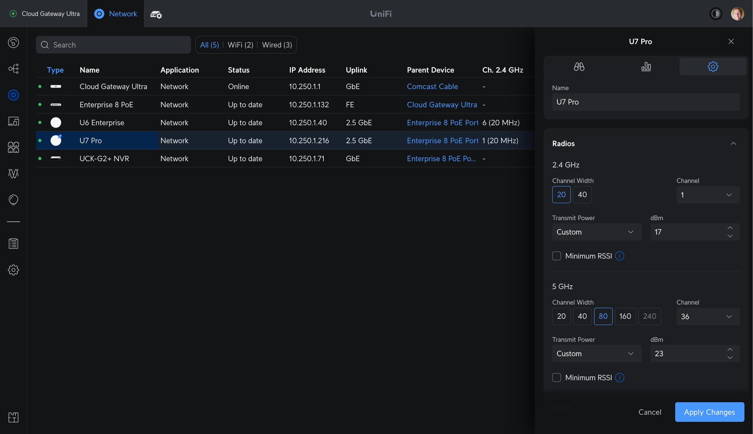
UniFi Radio Manager
Global AP settings used to be found under Settings → Wi-Fi, but now live within Radio Manager. In Radio Manager, there are five tabs. The Coverage, Connectivity, Environment, and Speed Test tabs provide information about your current network. It’s a good idea to look through them before and after making changes.
The Radios tab shows a list of every AP with filters for frequency band, wired and meshed backhaul, MIMO, and status. When you select a radio, a right-side panel pops up with controls. You can select multiple APs and change settings for them all at one time. The settings are the same as before: Channel width, channel, transmit power, and a toggle for minimum RSSI.
Channel Width allows you to set the channel width for each frequency band of your Wi-Fi radios. 20 MHz is the base channel width for modern Wi-Fi, but multiple channels may be bonded together to increase data rates and throughput.
2.4 GHz should almost always be set to 20 MHz. There is not enough space in the 2.4 GHz spectrum to reliably use 40 MHz channels, especially with multiple APs.
5 GHz can be set to 20, 40, 80, 160, and now with Wi-Fi 7, up to 240 MHz. The best option depends on how much you value AP and client density (20 MHz) vs. maximum throughput (80, 160, or 240 MHz). Some clients may not fully support 160 MHz channels in 5 GHz, which requires DFS. 240 MHz channels are exclusive to Wi-Fi 7 clients, but Wi-Fi 6 or older clients will just use a subsection of the channel if you select a 240 MHz width.
6 GHz can safely be set to 80 or 160 MHz. In the US there is 1200 MHz of available spectrum for these wide channels, and no requirement for DFS or AFC for 6 GHz low power indoor (LPI) access points such as the U6-Enterprise or U7-Pro. With Wi-Fi 7, 6 GHz channels can be up to 320 MHz, but the same asterisks apply as with 240 MHz channels in 5 GHz.


Transmit Power allows you to set TX power for your radios to low, medium, high, auto, or a custom value. If you think of an AP as a speaker, this is the volume slider. The actual dBm values for low, medium, and high are based on the AP model and what they are capable of.
Broadly speaking, higher transmit power means longer range, higher signal-to-noise, and higher throughput. Higher power levels can also increase co-channel or adjacent-channel interference, so it is a balancing act.
2.4 GHz signals travel longer distances, and through obstructions like walls or trees more effectively than 5 GHz or 6 GHz signals. In a multi-AP network, turning down 2.4 GHz transmit power helps balance the inherent difference in range. This can lead to better performance and more reliable roaming.
5 GHz and 6 GHz signals attenuate more rapidly and are more affected by obstructions, resulting in around half the range of 2.4 GHz. If you have a dense network with multiple APs, setting a unique channel and keeping 5 GHz TX power lower may be best. For those trying to achieve the most range and coverage from the APs they have, high 5 GHz and 6 GHz TX power can be set.
Recommendation: Auto is a good default, but usually results in maximum power. If setting manually, use the lowest power level that still results in good coverage and signal strength. Keep 2.4 GHz around 6 dBm lower than 5 GHz or 6 GHz in multi-AP networks if you want to keep their coverage area roughly the same.
Minimum RSSI tries to assist clients with roaming decisions and moving from one AP to another. When enabled, APs will disconnect clients when they reach a certain Received Signal Strength Indication (RSSI) value. Ubiquiti’s Understanding and Implementing Minimum RSSI does a good job at explaining the rest of the basics.
Typical Wi-Fi RSSI values are negative. The closer it is to zero, the stronger the signal is. A value of -80 dBm is a very weak signal, and a value of -40 dBm is a very strong signal.
If you’re running into issues with devices staying connected to a far away AP, you probably want to review your network as a whole, including AP placement and settings like transmit power. Minimum RSSI is another tool, but it won’t fix a badly designed and configured network. That said, if you’re still struggling with clients roaming to a nearby AP, enabling Minimum RSSI and setting a value around -70 dBm or so may be a good starting place. The right value depends on your setup and will vary from AP to AP.
AP and Wi-Fi Settings That Moved

These settings used to be part of the global AP rules, but have migrated to Settings → System → Advanced.
Wireless Meshing allows UniFi APs to connect to the network with a wireless connection to another AP, rather than Ethernet. This enables a hidden SSID on each AP, which other APs can connect to.
Mesh APs rely on wireless backhaul, but otherwise act like a normal UniFi AP. They can extend the range of your network, but offer lower throughput.
If you can’t run Ethernet to all of your APs and need to rely on wireless backhaul, you should leave this enabled. Otherwise, you can disable it to reduce SSID and management frame overhead.
Recommendation: Uncheck for networks where all APs have wired backhaul. Leave enabled for additional redundancy and a small hit to airtime utilization.
New WiFi Device Auto-Link allows wireless UniFi Protect cameras and some UniFi devices to be automatically visible for adoption. Previously this setting enabled a hidden “Element-xxxxxx” SSID, but it now enables a hidden SSID with no name. This makes it easier to set up those devices but can be disabled if you don’t need it.
Recommendation: Uncheck once your network is fully set up, or leave enabled if you are often adding new UniFi devices.
Connectivity Monitor Type controls what mesh APs attempt to reach to determine if they are online. This is only available when wireless meshing is enabled.
By default, it is the IP of their gateway, typically a UniFi or 3rd party router. You can change this to be any IP you’d like.
If the device fails to reach the destination, it will enter an “isolated” state, meaning it can’t reach the network. That usually happens when there is a misconfiguration, such as wireless meshing being turned off, or port or VLAN settings not being correct.
Recommendation: Leave at default unless you have a reason to change to a custom destination. Internal resources are better than public services or websites that rely on working Internet access.
Optimize Channelization (Nightly Channel Optimization) has moved around a few times, but currently lives under Settings → Wi-Fi. It is an automated process that looks at all connected UniFi APs and the RF environment they are in. It attempts to automatically pick the best channels for you and usually does a good job.
For high-density networks where careful channel planning is important, manual selection may help. For most networks, especially with less experienced administrators, auto-channel optimization usually leads to good results.
You can apply this to all APs, or only APs configured to auto channel.
Recommendation: Leave enabled if you prefer the ease of use, disable if you are manually setting channels.
Individual AP Settings and Manual Control
Increasing Wi-Fi Speed and Capacity
At the most basic level, you only want one AP per channel. If you have two APs on the same channel in the same area, they will conflict with each other.
Every Wi-Fi transmission requires the coast to be clear. All Wi-Fi devices (including APs themselves) take turns consuming airtime with their transmissions. When the channel is busy and another device is transmitting, they have to wait. Two devices transmitting on the same channel results in interference and retransmissions. This increases latency and reduces throughput and capacity.
One way to increase overall capacity is to use multiple APs, with unique channels for each. This allows for more devices to broadcast at a given time, and devices on AP #1 to not conflict with devices on AP #2. Another way is to increase channel width. Wider channels increase throughput, but can also create issues.
All of these factors make channel selection, channel width, transmit power, and access point placement some of the key things to focus on when building a network with multiple APs.
Radios: Channel, Width, and Power
2.4 GHz
2.4 GHz channel width should almost always be set to 20 MHz. In the US there are only 3 non-overlapping 20 MHz channels to use, 1, 6, or 11. There is one or two non-overlapping 40 MHz channels, depending on where you are in the world.
For a network with multiple APs, you should stick with 20 MHz and channels 1, 6, or 11. Pick one and try to keep other APs on that channel as far away as possible. 2.4 GHz signals travel further and are better at penetrating obstacles like walls or trees. Turn down your 2.4 GHz transmit power or spread out your APs if you still have too much overlap.
An example would be a two-story house with a basement. If you have one AP per floor, you’d pick channel 1 for the basement, channel 11 for the 1st floor, and channel 6 for the 2nd floor. If you add a 4th AP to cover the backyard, pick the channel with the weakest signal strength and least amount of interference. Adjust your AP placement and power levels to ensure even coverage and smooth AP-to-AP roaming.
5 GHz
The default channel width for 5 GHz is 40 MHz, and that is a good default. There are four non-overlapping 40 MHz channels, and eight more in DFS space. The wider the channel gets, the less unique channels you have to use.
The channel selection in UniFi defines the primary 20 MHz channel that beacon frames and other control traffic is sent on. With 40 MHz width, you’ll also be using the channel above or below. You may see this defined as “channel 38” or “channel 36+1”, but they all refer to the same thing.
Picking channel 36 and 40 MHz width will use both channels 36 and 40. Picking channel 36 and 80 MHz width will use channels 36, 40, 44, and 48. With that in mind, here are the number unique channels you can choose at each width:
20 MHz has nine: 36, 40, 44, 48, 149, 153, 157, 161, or 165
40 MHz has four: 38, 46, 151, or 159
80 MHz has two: 42 or 155
When you add in DFS space, you have several other channels to pick from:
Sixteen 20 MHz channels, for a total of 25
Eight 40 MHz channels, for a total of 12
Four 80 MHz channels, for a total of 6
For 160 MHz channels in 5 GHz, you always need to utilize DFS space. There are three non-overlapping channels available: 50, 114, and 163.
There is one 240 MHz channel: 130.
Configuring access point radio settings manually in the device settings side panel
For dense networks with 4+ APs, using 20 or 40 MHz width and creating a manual channel plan to minimize overlap usually leads to the best results. For normal home networks that prioritize speed, 40 or 80 MHz is usually a good balance. If you have modern clients, a use case that would benefit from several hundred Mbps, aren’t worried about interference and your Wi-Fi neighbors, or you just wanna go fast: try 160 MHz or 240 MHz.
Using 80 or 160 MHz channels in a multi-AP network requires dealing with DFS, or being limited to two unique 80 MHz channels. Not all devices support 160 MHz, and 160 MHz channels are the most susceptible to noise and interference. These wide channels trade range and noise for speed. You’ll get the most use for your gigabit connection, but 40 or 80 MHz channels may be a better balance overall. Sometimes it makes sense to mix and match, where you’d put a 160 MHz channel in your office, but use a more conservative 20 or 40 MHz channel on the outdoor AP that covers your backyard. Experiment and see what works best for you.
6 GHz
6 GHz is largely the same as 5 GHz, but there is no DFS. For low-power indoor APs like the U6-Enterprise or U6-Enterprise-In-Wall, there is no AFC requirement either. Power limits are set with a constant spectral density rather than a constant EIRP. What that means in practice is that there is no noise penalty for doubling a channel width in 6 GHz. With each +3 dB (doubling) of noise, the EIRP doubles as well. That means for 80, 160, and even 320 MHz width channels, 6 GHz is the best place for them.
If you have 6 GHz APs and 6 GHz devices, set a wide channel, high power, and let it rip. You will also need to enable WPA3, which is required for 6 GHz operation. 6 GHz also has a slightly worse range and penetration than 5 GHz, so it will quickly fall off in strength when it passes through a wall or floor.
Individual AP Settings
Getting outside of Radio Manager and bringing up an individual AP in the Devices tab shows a few other settings.
Band Steering can be set to off, prefer 5 GHz, and balanced. This is separate from the Band Steering setting that is set on the network level, which uses a less disruptive method to encourage clients to move off of 2.4 GHz. This per-AP setting is available as well if you have certain APs that are stickier than others.
With off, the AP doesn’t do anything to encourage clients to join 5 GHz, and clients may prefer to join the 2.4 GHz radio due to it having a longer range and a higher RSSI. Those clients may be closer to another AP and a stronger 5 GHz radio, but a lot of times the Wi-Fi client device will stay connected to the 2.4 GHz radio. Setting band steering to prefer 5 GHz can sometimes help with that. It can also cause issues with some IoT or 2.4 GHz-only devices, so balanced is sometimes a safer choice. This is one more knob to turn when you’re having issues with roaming.
IP settings are where you define the management IP address of the AP. By selecting Network Override, you can have it be in a virtual network rather than the default, untagged network. When doing this, make sure the port you are connecting the AP to is a trunk port, and it has access to the virtual network you are assigning. By default, all networks are allowed. Setting an invalid virtual network or IP configuration will prevent your UniFi Network controller from being able to reach or manage your device. That may require a port change or AP reset to fix.
Under network override are the common settings you’d expect: IP, subnet mask, gateway, DNS, and DNS suffix. Below that you have a few options which vary by AP model, but that is where you’d control the LED, SNMP, copy an existing configuration from another AP, enter the debug terminal, do a manual firmware update, flash the LED to locate it, restart or remove the device from your network.
The old “legacy” user interface has been going away for a long time. Turning it on involves a warning that certain features aren’t supported, and Ubiquiti would really prefer you use the new interface for everything. Going forward, all settings and development focus is on the new UI, and the legacy UI is being left to rust. These settings are missing in the new interface, or have been moved/renamed.

RIP Legacy UI
Apply Guest Policies is now controlled by Hotspot 2.0 toggle for Captive Portal or Passpoint, and was previously controlled by setting the network type to guest.
Multicast and Broadcast Filtering or Block LAN to WLAN Multicast and Broadcast Data are now Multicast and Broadcast Control, under settings → Wi-Fi.
Beacon Country - add 802.11d county roaming enhancements is not shown in the new UI.
TLDS Prohibit - block Tunneled Link Direct Setup (TDLS) connections is not shown in the new UI.
Point to Point - also referred to as P2P is not shown in the new UI.
P2P Cross Connect - allow wireless stations to connect to each other through AP using P2P is not shown in the new UI.
Send beacons at 1 Mbps is now handled with the minimum data rate control settings.
User Group is now called bandwidth profile, for restricting maximum bandwidth for connected client devices.
L2 Isolation is now called Client Isolation, and enabled by default on guest networks.
Legacy Support - Enable legacy device support (i.e. 11b) is handled by the minimum data rate control settings.
High Performance Devices or Connect high performance clients to 5 GHz only is now controlled by the band steering setting.
One last thing to keep in mind: Sometimes, the best solution to a wireless problem is a wire.


All my charts for comparing Ubiquiti’s models of UniFi Gateways, Consoles, Wireless Access Points, and Switches. Last updated in December 2024 for the Enterprise Fortress Gateway, UXG-Enterprise, Enterprise Campus switches, and E7 Enterprise Wi-Fi 7 access points.